

+86-18913642321

Liduck.1985@163.com
DAWANG GEARBOX

Views: 0 Author: Site Editor Publish Time: 2026-10-15 Origin: Site


Drive design frequently presents a core engineering conflict for modern industrial applications. You must achieve high torque transmission within severely limited radial or axial space. Industrial environments demand immensely powerful machinery. However, these facilities rarely offer unlimited physical footprints for equipment installation. This spatial restriction frustrates system integrators and mechanical engineers daily. Equipment must perform reliably without protruding into walkways or adjacent machine frames. A bulky drive system easily disrupts workflow and creates severe safety hazards.
While planetary and right-angle gearboxes certainly have their place, they cannot solve every spatial constraint. The Parallel Shaft Gearbox remains the definitive choice for specific narrow footprint challenges. It also excels continuously in heavy industrial environments where downtime is unacceptable. In this article, you will explore the structural advantages of these unique drive units. We will examine their primary industrial applications in detail. Finally, you will learn key sizing frameworks to ensure optimal mechanical performance and equipment longevity.
Space Optimization: Parallel shaft gearboxes provide high torque density in exceptionally narrow, flat footprints, ideal for tight installation envelopes.
High Efficiency: Helical gear arrangements within these units typically yield 96–98% efficiency per stage, outperforming worm gear equivalents.
Core Applications: Dominant in continuous-operation systems like bulk material conveyors, agitators, cranes, and intralogistics packaging lines.
Evaluation Focus: Selection depends heavily on required service factors, thermal capacity, and mounting style (solid vs. hollow shaft) rather than just theoretical torque.
To understand the widespread industrial adoption of these units, we must define their fundamental architecture. Inside the housing, the input and output shafts align on strictly parallel axes. This specific configuration permits a distinctively flat, rectangular gearbox housing. Conventional inline drives require significant axial length, extending far behind the motor. Right-angle drives project outward radially, consuming valuable lateral space. Conversely, the parallel layout allows the entire drive package to hug the machine frame tightly.
This intelligent design actively solves narrow physical clearance problems. When equipment operates in confined corridors, protruding components pose severe safety risks. A parallel shaft gearbox offers an undeniably superior power-to-space ratio. You receive substantial torque density tucked neatly against the primary chassis. Facility managers appreciate this design because it maximizes usable floor space. It prevents clumsy interference between operators and moving machinery components.
Furthermore, these units deliver exceptional mechanical efficiency. Parallel helical gears utilize a smooth rolling action. They avoid the harsh sliding friction found in other designs. This dramatically reduces internal heat generation compared to low-efficiency alternatives like worm drives. Helical gear arrangements easily maintain peak performance during demanding 24/7 operational cycles. They manage continuous duty applications brilliantly without excessive energy loss. Over an entire operational year, this efficiency translates directly into lower electrical consumption. You benefit from cooler operating temperatures and extended lubricant life.
Heavy industry relies entirely on robust, dependable power transmission. Let us examine three critical areas where these units consistently dominate the market.
Long-distance conveyor systems in mining and quarrying face distinct business problems. Operators require sustained, massive torque over extensive distances. These belt systems operate in remarkably harsh, dusty environments. Moreover, lateral space along the conveyor bed often remains scarce due to walkways and structural supports. An industrial parallel shaft gearbox meets these strict success criteria perfectly. It provides incredibly high overhung load capacity. Furthermore, it allows for simplified hollow-shaft mounting directly onto the head pulley. This direct-mount approach eliminates bulky base plates. It also removes the need for complex flexible couplings, simplifying the overall conveyor head station.
Chemical processing and wastewater treatment present another extreme mechanical environment. Mixing highly viscous materials creates intense, continuous radial and axial loads. Fluid dynamics shift constantly, causing severe vibrations. Standard drives fail quickly under such chaotic stress. Success here requires robust bearing spans inside the gearbox housing. Manufacturers often provide customized output shafts designed specifically for mixing loads. The parallel shaft design naturally prevents harmful internal deflection under heavy dynamic loads. It keeps the gear mesh perfectly aligned. This stability ensures the mixing process remains safe and reliable around the clock.
Port terminals and steel mills demand absolute lifting safety. The core business problem revolves around reliable load-holding and smooth lifting operations. You simply cannot tolerate catastrophic gear failure or excessive backlash in overhead applications. Dropped loads cause immense damage and risk human life. These flat gearboxes integrate seamlessly into winch drums. They easily accept modular additions like mechanical backstops and fail-safe brakes. They ensure consistent high-torque delivery at critically low lifting speeds. Crane operators rely on this smooth power delivery for precise load positioning.
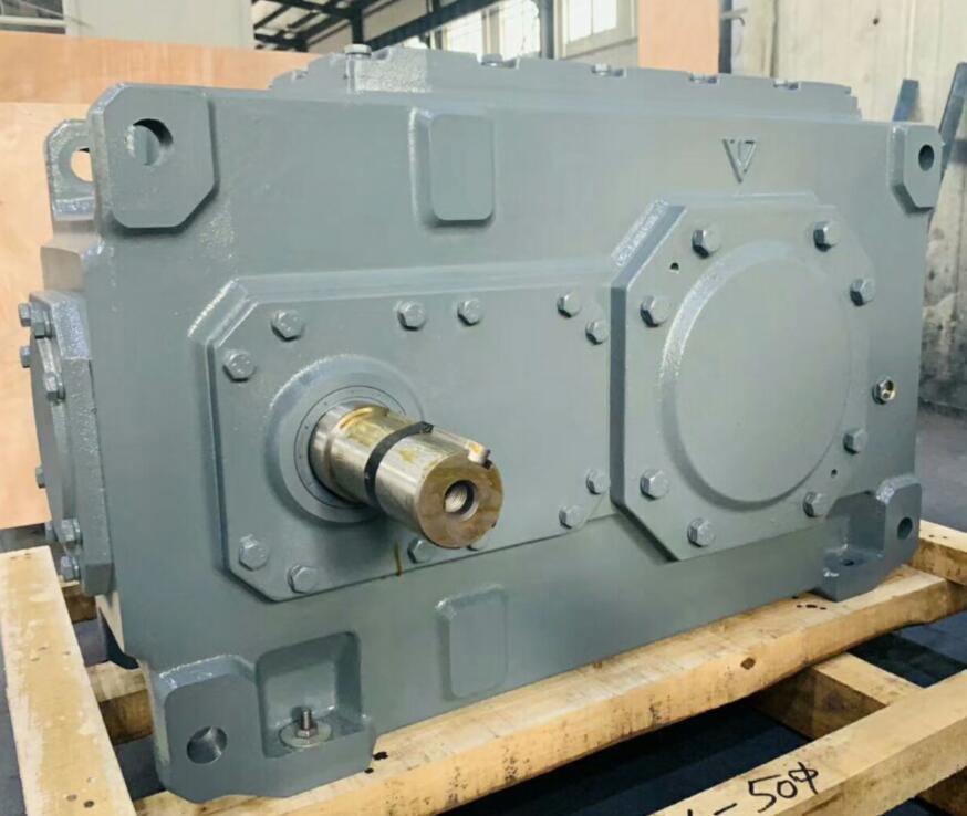
Modern factory layouts rigorously prioritize floor space optimization. Every square meter carries a distinct financial value. Let us review specific automated scenarios where a narrow footprint becomes absolutely mandatory.
Intralogistics and Sorting Systems: Dense e-commerce warehouse environments feature multiple conveyor lines running side-by-side. Facilities cannot afford wide gaps between tracks just to accommodate bulky electric motors. Cross-belt sorters and merging conveyors demand tightly packed components. The exceptionally flat profile of a parallel shaft speed reducer prevents physical interference between parallel conveyor tracks. Engineers can place drive units incredibly close together. This layout maximizes sorting density per square meter and increases overall facility throughput.
Packaging Machinery: Food and beverage packaging lines require highly compact machine frames. Servo-driven cartoning machines need precise synchronization. Bulky external drive protrusions disrupt operator workflows. They also create dangerous pinch points and cleaning obstacles. The ideal solution involves easy, seamless integration directly into the machine chassis. You can mount these drives securely using standardized torque arms or B14 flange mounts. This streamlined layout maximizes aisle space. It allows maintenance personnel to navigate the packaging floor safely and efficiently.
Automated Guided Vehicles (AGVs): Mobile robotics represent the frontier of modern manufacturing. AGVs require extreme power density packed into tiny wheel-drive chassis. Parallel designs allow the motor and gearbox to sit flat against the vehicle frame. This maximizes internal space for battery packs and lifting mechanisms.
Mechanical engineers frequently debate between parallel and planetary configurations. Both designs deliver substantial industrial torque. Yet, they serve entirely different spatial and operational requirements.
First, consider the physical footprint and mounting orientation. Planetary gears feature a cylindrical, axial footprint. They extend linearly outward from the motor shaft. This creates a long, tube-like shape. In sharp contrast, a parallel shaft unit provides a flat, rectangular footprint. It mounts flush against the equipment side wall. If you lack axial length but possess vertical space, the parallel design wins easily.
Next, evaluate load distribution and maintenance realities. Planetary drives offer incredible torque density because load spreads across multiple planet gears simultaneously. However, their internal epicyclic stages prove highly complex to rebuild. Field repairs remain notoriously difficult for planetary units. Conversely, parallel units allow much easier internal access. Mechanics can split the housing or remove side covers for bearing and seal replacement. Maintenance teams at remote industrial sites greatly prefer this accessible layout. It simplifies standard service intervals and drastically reduces operational downtime.
Finally, weigh initial cost against long-term performance. Planetary units often carry premium price tags due to complex internal machining requirements. The parallel shaft unit stands out as a pragmatic, cost-effective choice. It perfectly suits high-torque applications where spatial limitations exist, but extreme cylindrical compactness is not strictly necessary. You achieve outstanding durability without over-engineering the application.
Gearbox Architecture Comparison
Feature | Parallel Shaft Gearbox | Planetary Gearbox |
|---|---|---|
Footprint Geometry | Flat, narrow, rectangular | Cylindrical, long, axial |
Maintenance Access | Highly accessible in the field | Complex, often requires workshop |
Efficiency | 96-98% per stage | 95-97% per stage |
Cost Profile | Moderate to highly cost-effective | Premium pricing |
Proper application requires precise, methodical engineering calculations. You must avoid sizing a drive purely on the motor's nominal horsepower rating.
Engineers must strictly apply established service factors, such as those defined by AGMA (American Gear Manufacturers Association) standards. You need to account for anticipated shock loads and true duty cycles. A conveyor belt operating smoothly 10 hours daily requires completely different sizing than a rock crusher running continuously for 24 hours. A uniform load might use a 1.0 service factor. A heavy shock load might demand a 2.0 or higher multiplier. Undersizing inevitably leads to rapid gear tooth fatigue and catastrophic failure.
Furthermore, closely evaluate thermal versus mechanical horsepower limits. Overheating poses a significant implementation risk in enclosed spaces. A gearbox might easily survive the applied mechanical loads. However, it will fail thermally if ambient temperatures and continuous runtimes exceed the housing's heat dissipation limits. The oil degrades rapidly under excessive heat. You may need to specify supplemental cooling systems. Shaft-driven cooling fans or external oil coolers work well in hot environments.
Finally, navigate the mechanical mounting complexities carefully. Solid shaft outputs require flexible couplings and meticulous laser alignment. This traditional method adds lateral length to your setup. Alternatively, hollow shafts slip on directly to the driven machine using shrink discs. This modern approach saves tremendous space. It applies a massive 360-degree radial clamping force. However, it demands precise driven shaft tolerances (such as h6 or k6). Poor machining tolerances will prevent a secure grip and cause severe fretting corrosion over time.
Parallel shaft gearboxes successfully balance high mechanical efficiency, formidable torque capacity, and space-saving flat geometry.
They consistently outperform high-friction alternatives in heavy-duty, continuous-running applications like bulk conveyors and industrial mixers.
Planetary drives offer immense torque density, but parallel units provide superior field maintenance access and lower lifecycle replacement costs.
Proper selection requires rigorous attention to AGMA service factors and environmental thermal dissipation limits.
Before contacting a manufacturer, engineers should carefully document their available installation envelope dimensions. You must also record peak ambient operating temperatures and calculate exact duty cycle requirements. Proper upfront documentation prevents costly specification errors during procurement.
Submit your CAD constraints and operational parameters to our engineering team today. We will happily review your data. Our experts will quickly provide a customized parallel shaft speed reducer sizing recommendation tailored perfectly to your specific project needs.
A: These units deliver exceptional mechanical efficiency. A standard design typically achieves a 96–98% efficiency rate per gear stage. Unlike worm drives, helical gears rely on smooth rolling contact rather than harsh sliding friction. This minimizes internal power losses and prevents excessive heat buildup during continuous operation.
A: Yes, you can mount these units vertically. However, this orientation requires modified lubrication strategies. Standard splash lubrication often fails to reach the top bearings in a vertical stance. You must implement forced lubrication systems or maintain specific higher oil levels to prevent top-bearing starvation and premature failure.
A: The primary advantage lies in superior energy efficiency. Parallel helical gears do not suffer the heavy sliding friction inherent to worm drives. This drastically reduces internal heat generation. Over years of continuous industrial operation, this high mechanical efficiency results in significantly lower electrical energy costs for your facility.


